- Created by Vladimir Stanković on 14 04, 2016
This section offers a brief guide for setting up NetFlow on a Cisco router or switch. For more detailed information, refer to the Cisco website.
| Device | Supported |
|---|---|
| Cisco 800, 1700, 2600 | Yes |
| Cisco 1800, 2800, 3800 | Yes |
| Cisco 4500 | Yes |
| Cisco 6500 | Yes |
| Cisco 7200, 7300, 7500 | Yes |
| Cisco 7600 | Yes |
| Cisco 10000, 12000, CRS-1 | Yes |
| Cisco 2900, 3500, 3660, 3750 | Yes |
Software Platform Configuration
The following is an example of a basic router configuration for NetFlow. NetFlow basic functionality is very easy to configure. NetFlow is configured on a per interface basis. When NetFlow is configured on the interface, IP packet flow information will be captured into the NetFlow cache. Also, the NetFlow data can be configured to export the NetFlow data to the NetFlow Server.
1. Configuring the interface to capture flows into the NetFlow cache. CEF followed by NetFlow flow capture is configured on the interface
     Router(config)# ip cef
     Router(config)# interface ethernet 1/0
     Router(config-if)# ip flow ingress
Or
Router(config-if)# ip route-cache flow
Either ip flow ingress or ip route-cache flow command can be used depending on the Cisco IOS Software version. IP flow ingress is available in Cisco IOS Software Release 12.2(15)T or above.
2. For exporting the NetFlow cache to the NetFlow Server. A version or a format of the NetFlow export packet is chosen and then the destination IP address of the server (in this example 172.22.23.7). The 2055 is the UDP port the NetLow Server will use to receive the UDP export from the Cisco device. 2055 is a default value, you can change this as described in chapter Configuring the service settings on page 141 (Collection port).
     Router(config)# ip flow-export version 9
     Router(config)# ip flow-export destination 172.22.23.7 2055
More Information on NetFlow Configuration is available at Cisco website.
Cisco Catalyst 6500 Series Switch Platform NetFlow Configuration
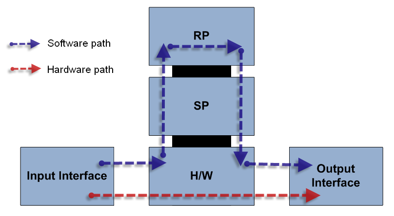
The following is an example of NetFlow on a Cisco Catalyst 6500 Series Switch. The Cisco Catalyst 6500 Series Switch has two aspects of NetFlow configuration, configuration of hardware based NetFlow and software NetFlow. Almost all flows on the Cisco Catalyst 6500 Series Switch are hardware switched and the MLS commands are used to characterize NetFlow in hardware. The MSFC (software based NetFlow) will characterize software based flows for packets that are punted up to the MSFC.

Figure above shows the concept of two paths for NetFlow packets, the hardware (red) and software (blue) paths and the configuration for each path. Normally on Cisco Catalyst 6500 Series Switch both hardware and software based NetFlow is configured.
The hardware switched flows use the MLS commands to configure NetFlow. Remember that for the hardware based flows NetFlow is enabled on all interfaces when configured.
mls aging normal 32 (Set aging of inactive flows to 32 seconds)
mls flow ip interface-full (Optionally configure a flow mask)
mls nde sender version 5 (Specify the version for export from the PFC)
mls nde interface (send interface information with the export, command available by default with Supervisor720/Supervisor 32)
The following is the configuration for NetFlow on the MSFC for software based flows. This configuration is equivalent to what is shown in Cisco Catalyst 6500 Series Switch Platform NetFlow Configuration. The user configures NetFlow per interface to activate the flow characterization and also configures an export destination for the hardware and software switched
flows.
interface POS9/14
     ip address 42.50.31.1 255.255.255.252
     ip route-cache flow (also ip flow ingress can be used)
     ip flow-export version 5 (The export version is setup for the software flows exported from the MSFC)
     ip flow-export destination 10.1.1.209 2055 (The destination for hardware and software flows is specified)
More Information on the Cisco Catalyst 6500 Series Switch NetFlow Configuration can be viewed at Cisco website.
- No labels